
MIMO vs MISO vs Single-Axis Vibration Testing
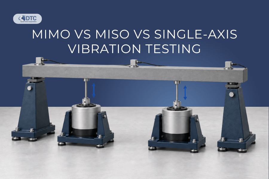
When does a vibration test really need MIMO control?
It is an important question because adding more shakers, accelerometers and control channels does not automatically make a vibration test more accurate or more representative.
For many products, a conventional single-axis test is exactly what the qualification programme requires. For others, using only one excitation direction at a time can miss interactions that occur when a structure is loaded simultaneously at several points or along several axes.
The choice between single-axis, MISO and MIMO vibration testing should therefore be based on the physical test environment, the structure of the device under test and the required control strategy—not simply on the number of available shaker channels.
There is also an important terminology point that is often overlooked:
Single-axis describes the physical direction of excitation. SISO, MISO and MIMO describe the control architecture.
A single-axis test can use multiple control accelerometers. Multiple shakers can also act along the same physical axis. Understanding this distinction is the first step toward selecting the correct vibration control system.
What is the difference between single-axis, MISO and MIMO vibration testing?
At a practical level:
Single-axis vibration testing excites the test article primarily along one physical direction at a time.
SISO control uses one measurement input and one drive output.
MISO control uses multiple measurement or control inputs with one shaker drive output.
MIMO control uses multiple measurement inputs and multiple independently controlled drive outputs.
The terminology comes from control-system architecture rather than simply the number of accelerometers attached to the test object.
| Test architecture | Measurement/control inputs | Independent drive outputs | Typical configuration |
|---|---|---|---|
| SISO | 1 | 1 | One shaker, one control accelerometer |
| MISO | Multiple | 1 | One shaker, several control/monitoring points |
| MIMO | Multiple | Multiple | Multiple shakers and multiple control points |
| Multi-axis MIMO | Multiple | Multiple | Multiple shakers acting along two or more axes |
| 6-DOF MIMO | Multiple | Multiple | Control of three translations and three rotations |
MISO has long been used in vibration control to describe configurations where several control transducers feed a single shaker-output control system, while MIMO extends the architecture to multiple independently driven exciters.
Single-axis vibration testing: the starting point
Traditional vibration qualification is commonly performed one axis at a time. The device under test is mounted to an electrodynamic or servo-hydraulic shaker and excited along one direction—typically X, Y or Z. The product may then be repositioned so that the remaining axes can be tested sequentially. For many qualification programmes, this remains an effective and appropriate method.
A typical single-axis system includes:
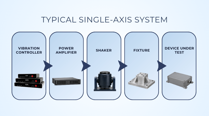
Vibration controller → power amplifier → shaker → fixture → device under test
One or more accelerometers measure the response and provide feedback to the controller.
DTC’s VENZO 800 Series Vibration Controller is designed for shaker-based sine, random, shock and field data replication testing on electrodynamic and servo-hydraulic systems. Depending on the model, the VENZO 800 platform provides up to 8, 32 or 64 input channels, with one or two drive outputs.

Single-axis does not necessarily mean one accelerometer
This is an important distinction. A test can remain physically single-axis while using several accelerometers.
For example, imagine a large electronic enclosure attached to a vertical shaker.
One accelerometer might be positioned:
At the fixture interface
At the left side of the enclosure
At the right side
On a sensitive internal component
The shaker still moves primarily along one axis. However, several measurement locations can be used to understand how the vibration is distributed across the structure.
Depending on the control strategy, the controller might use:
One primary control accelerometer
The average of several control points
A maximum-response strategy
A minimum-response strategy
Weighted control
Separate limiting channels
This is where the distinction between simple SISO and MISO control becomes useful.
What is MISO vibration control?
MISO means Multiple Input, Single Output.
In a vibration-control application, multiple accelerometer signals are available to the control system, but there is still only one independently controlled shaker drive output.
A simplified MISO setup looks like this:
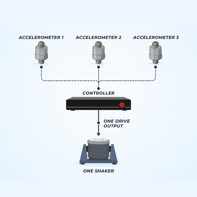
The multiple measurements allow the controller to make a more informed control decision while the system still has only one independent excitation command.
This architecture is particularly useful when one measurement point is not sufficient to represent what is happening across the fixture or test object.
When is MISO useful?
Consider a long structural component mounted on a shaker. If the test is controlled from only one accelerometer, the vibration at that point may match the reference perfectly while another part of the structure experiences a much higher response because of a resonance. Adding several measurement points makes it possible to identify these differences.
MISO control can therefore be useful for:
Large fixtures
Flexible structures
Long test articles
Large electronic assemblies
Battery packs or modules
Structures with known resonances
Tests requiring several control or limiting points
Situations where one accelerometer does not adequately represent the input
MISO can improve visibility of the structure’s behaviour without requiring several independently driven shakers.
MISO is not the same as MIMO
This is one of the most important distinctions when selecting a vibration controller. Adding ten accelerometers to a single-shaker test does not make the system MIMO.
The key question is: How many independent drive signals are being controlled?
If several measurements ultimately regulate one shaker drive signal, the architecture remains single-output.
If several independently controlled drive signals act on the structure simultaneously, the problem becomes multi-output and may require MIMO control.
What is MIMO vibration testing?
MIMO means Multiple Input, Multiple Output.
In MIMO vibration testing, the controller measures several response points while simultaneously controlling several independent shaker or actuator outputs.
A simplified example is:
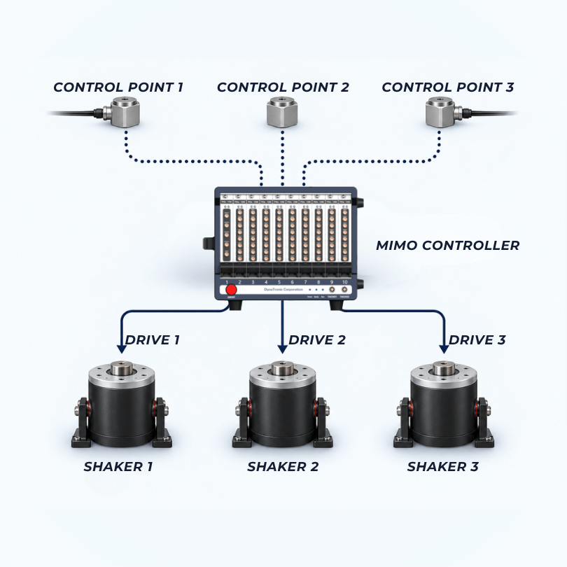
But the real challenge is not simply generating several drive signals.
The shakers and test object are mechanically connected. Changing the output of one shaker can alter the response measured at several control locations. That interaction is what makes MIMO control fundamentally different from operating several independent single-axis controllers.
Research on multi-input vibration testing describes MIMO control as a way of simultaneously exciting structures at several points or degrees of freedom, with the interactions between the excitation sources forming part of the control problem. Multi-axis excitation can also excite structural modes simultaneously rather than sequentially. See the Sandia/OSTI technical work on multiple-input vibration testing.
Why can't several shakers simply be controlled independently?
Imagine two shakers connected to the same large test article.
Shaker A generates force at one point.
That force travels through the test article and changes the acceleration measured not only near Shaker A, but also near Shaker B.
At the same time, Shaker B affects the measurement near Shaker A.
The structure therefore creates a coupled system:
Drive A affects Response A and Response B.
Drive B affects Response A and Response B.
With more shakers and more control locations, the number of interactions increases further.
This behaviour is called cross-coupling.
Multiple-shaker research has shown that exciters can couple through the structural dynamics of the device under test, which is why simply treating every shaker as an independent control loop can produce control errors or unintended loading.
A MIMO controller must therefore consider the relationship between all relevant drive signals and control responses together.
Understanding the MIMO control matrix
For a simplified two-shaker system, the controller must understand four relationships:
Shaker 1 → Control Point 1
Shaker 1 → Control Point 2
Shaker 2 → Control Point 1
Shaker 2 → Control Point 2
This can be represented as a transfer matrix.
With four outputs and four control points, there can be sixteen drive-to-response relationships.
With eight outputs and eight control points, there can be sixty-four.
That is why MIMO vibration control requires significantly more processing and system identification than a conventional single-output test.
The controller determines how the complete structure responds and then calculates the combination of drive signals required to produce the desired response at the control locations.
Multi-shaker does not always mean multi-axis
Another important distinction is between multiple exciters and multiple axes.
Several shakers can operate:
Along the same axis
For example, two vertical shakers may support a large structure that cannot be excited adequately by one shaker.
This is often referred to as a multiple-exciter, single-axis configuration.
Along different axes
Shakers may act simultaneously in:
X
Y
Z
This allows the test system to reproduce vibration from several directions at the same time.
In combined translational and rotational degrees of freedom
More advanced systems can reproduce:
Translation along X
Translation along Y
Translation along Z
Rotation about X
Rotation about Y
Rotation about Z
This produces a six-degree-of-freedom, or 6-DOF, test environment.
Sandia research has demonstrated closed-loop six-degree-of-freedom random vibration control using multiple independent electrodynamic exciters to control all three translations and three rotations. See the six-DOF shaker evaluation.
What is six-degree-of-freedom vibration testing?
A rigid body in three-dimensional space can move in six fundamental ways.
Three translations
X — forward/backward
Y — left/right
Z — up/down
Three rotations
Roll
Pitch
Yaw
Together, these represent six degrees of freedom.
Real operating environments are rarely perfectly one-dimensional.
A vehicle component, aircraft system, spacecraft structure or large mechanical assembly may experience forces and moments from several directions simultaneously.
Research into multi-axis vibration testing therefore examines whether reproducing several degrees of freedom simultaneously can better approximate certain real dynamic environments than sequential single-axis excitation.
However, this does not mean every vibration test should become 6-DOF.
The additional complexity must provide a meaningful engineering benefit.
Why does cross-coupling matter?
Cross-coupling occurs when excitation applied at one location or direction produces a response somewhere else in the system.
Some amount of cross-axis or cross-point response exists in almost every real structure.
For example:
Vertical excitation may create lateral motion.
One shaker may excite a mode close to another shaker.
A flexible fixture may twist.
A large test article may transfer force between attachment points.
One structural mode may involve motion in several directions simultaneously.
In a conventional single-axis test, much of this behaviour is treated as response.
In MIMO control, some of these interactions become part of the active control problem.
This is why MIMO control cannot normally be reduced to several separate scalar controllers operating side by side.
Phase: when timing between channels matters
Amplitude is only part of a multi-shaker test. The relative phase between signals can determine how forces combine.
Imagine two shakers moving the same fixture. If they move in phase, their forces may reinforce one another. If one moves in the opposite direction at the same moment, the resulting structural loading can be completely different. Between these two conditions are many possible phase relationships.
In MIMO sine testing, engineers may therefore need to define not only the amplitude at several control points but also the phase relationship between them.
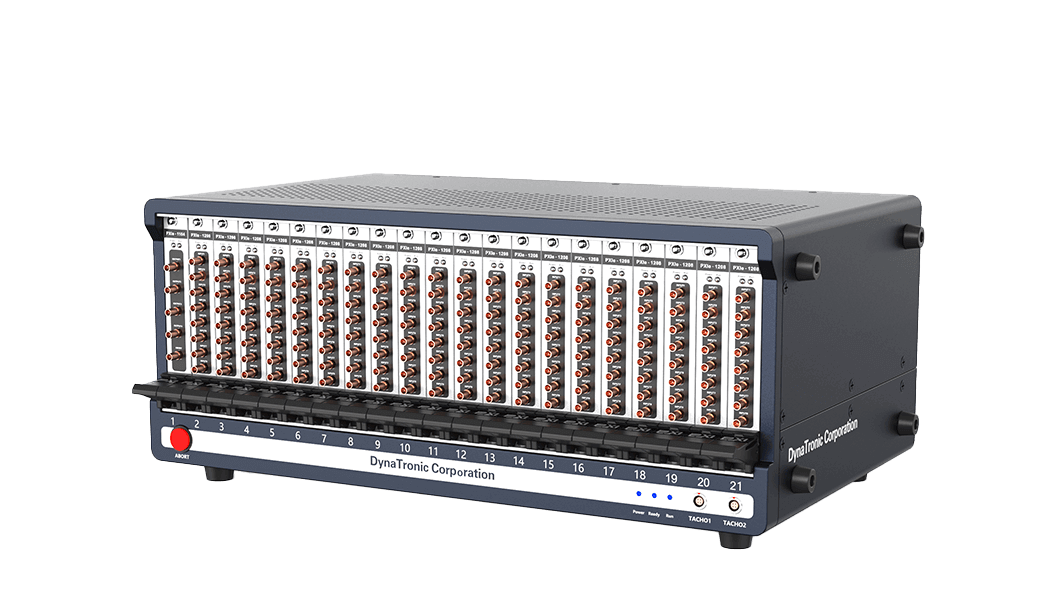
DTC’s VESSTA MIMO controller allows multiple control points to use different sine reference spectra and defined phase relationships during MIMO sine testing.
Coherence in MIMO random vibration testing
Random MIMO control introduces another important parameter: coherence.
In practical terms, coherence helps describe how strongly the random signals at different control points are related.
Two signals may be:
Highly correlated
Partially correlated
Largely independent
This matters because a real multi-axis environment does not necessarily produce identical random motion in every direction.
A MIMO random specification can therefore include not only the auto-spectral density at individual control points, but also cross-spectral information describing relationships between channels. Technical work on MIMO vibration testing uses cross-spectral density terms to represent these relationships, including phase and coherence information.
DTC’s VESSTA MIMO random software supports different random reference spectra at multiple control points and checks the rationality of configured coherence and phase relationships.
Why unrealistic coherence can create a bad test specification
A MIMO target must be physically achievable.
Suppose a specification demands:
A certain PSD at Point A
A different PSD at Point B
A fixed phase relationship
A coherence value that conflicts with those requirements
The resulting target matrix may not represent a physically consistent environment.
The test controller can only work with a mathematically and mechanically achievable combination of responses.
This is one reason MIMO test definition requires more engineering preparation than simply copying several independent PSD curves into the software.
The reference matrix should ideally come from:
Field measurement
Validated analytical modelling
Previous test data
A recognised qualification specification
An engineering-derived target with documented assumptions
Single-axis versus simultaneous multi-axis testing
One of the main reasons engineers consider MIMO is that real structures can respond differently when several directions are excited simultaneously.
Consider a bracket mounted in a vehicle.
During operation it may experience:
Vertical road input
Lateral chassis movement
Longitudinal acceleration
Engine or motor vibration
Traditional testing might apply:
X-axis random vibration
Reorient the specimen
Y-axis random vibration
Reorient again
Z-axis random vibration
This is straightforward and may be exactly what the qualification standard requires.
A simultaneous multi-axis test attempts instead to reproduce several directional inputs at the same time.
The resulting stress state and modal participation may differ because several structural modes can be excited together. Research from U.S. national laboratories has investigated multi-axis testing specifically because multi-degree-of-freedom excitation can reproduce aspects of real field loading that sequential single-axis testing does not.
Does MIMO make vibration testing more realistic?
Sometimes—but not automatically.
MIMO is more representative only when the input specification and physical test arrangement are themselves representative of the actual environment.
A poorly defined MIMO test can be less meaningful than a well-designed single-axis test.
To justify MIMO, engineers should be able to answer questions such as:
Does the real environment contain simultaneous multi-point or multi-axis excitation?
Are the relationships between those inputs known?
Are cross-spectral or phase relationships available?
Does sequential single-axis testing fail to reproduce an important structural response?
Is the test article large enough to require several excitation points?
Does the qualification requirement allow or require simultaneous excitation?
Can the fixture reproduce the intended boundary conditions?
If the answer to these questions is no, additional control complexity may provide little useful benefit.
Parallel-force multi-shaker testing
Not all MIMO applications involve different axes. A large test object may require two or more shakers operating in parallel along the same direction.
For example:
Shaker A ↑ Shaker B ↑
Both shakers may support one large fixture or structure.
This can be necessary when:
One shaker cannot provide sufficient force
The specimen is physically too large for one exciter
Force needs to be distributed across several attachment points
Boundary conditions require multiple excitation locations
However, mechanically linking several exciters introduces important challenges. The shakers may not experience identical loads. A structural resonance can change the force distribution between them. One shaker can effectively push against another if the control signals are poorly coordinated.
The control system must therefore consider the combined shaker–fixture–specimen dynamics rather than assuming that equal drive voltages will produce equal forces or equal motion.
Multi-shaker experimental research has documented the fact that shakers attached to the same DUT interact through its structural dynamics.
Multi-point control: when one control accelerometer is not enough
Whether the system is MISO or MIMO, control-point selection matters. A large fixture may not behave like a perfectly rigid table.
Suppose four accelerometers are installed at the corners of a large fixture.
At a low frequency, all four might measure nearly identical acceleration.
Near a fixture resonance:
Corner 1 may be above reference.
Corner 2 may be near reference.
Corner 3 may be below reference.
Corner 4 may show significant phase shift.
Controlling from only one corner could therefore misrepresent the input experienced by the rest of the specimen.
The engineer may need to consider:
Averaging
Weighted averaging
Maximum control
Minimum control
Independent reference points
Limiting or notching
Full MIMO control
The correct method depends on what the control points physically represent.
More control channels are useful only when their role in the test has been clearly defined.
SISO, MISO and MIMO in modal testing
The same terminology also appears in experimental modal analysis, although the objective differs from qualification vibration control.
Modal testing uses controlled excitation and measured responses to identify structural properties such as:
Natural frequencies
Mode shapes
Damping
Frequency response functions
Possible arrangements include:
SISO — Single Input, Single Output
One excitation point and one measured response.
SIMO — Single Input, Multiple Output
One excitation point with responses measured at several locations.
This is common when one shaker excites the structure while multiple accelerometers record its response.
MISO — Multiple Input, Single Output
Several excitation inputs are considered relative to one response.
MIMO — Multiple Input, Multiple Output
Several excitation points and several response locations are analysed simultaneously.
DTC’s TEN-M Modal Shakers are designed for experimental modal analysis, including SISO, MISO, SIMO and MIMO modal testing configurations.
For large or complex structures, multiple exciters can help distribute energy and excite modes that might be difficult to observe using one excitation location alone.
When is MIMO vibration testing required?
MIMO should be considered when the test problem genuinely contains several interacting excitation paths.
Typical situations include the following.
1. Multi-axis environmental reproduction
The measured field environment contains simultaneous vibration in X, Y and Z—or includes rotational motion—and reproducing these relationships matters to the test objective.
Possible examples include:
Vehicle structures
Aerospace equipment
Spacecraft hardware
Defence equipment
Large machinery
Transport systems
2. Large or heavy test articles
One shaker cannot provide enough force or cannot reproduce the required boundary conditions across the complete specimen.
Several coordinated exciters may be required.
3. Several attachment points receive independent excitation
A structure is supported or excited at multiple locations in its real installation.
Testing through only one point would significantly change the structural loading.
4. Cross-coupling is significant
Motion at one excitation point strongly affects other controlled locations, making separate independent controllers unsuitable.
5. Phase relationships are part of the requirement
The relative timing between inputs affects structural response and must be controlled.
6. Cross-spectral relationships must be reproduced
The field environment has measured coherence and phase relationships between several input channels.
7. Six-degree-of-freedom reproduction is required
The objective is to reproduce translational and rotational motion simultaneously.
When is MIMO unnecessary?
This question is just as important.
A sophisticated MIMO system should not be chosen simply because it is available.
Conventional single-axis or MISO control may be preferable when:
The test standard explicitly requires sequential single-axis testing
The specimen is small relative to the shaker table
One shaker provides sufficient force and motion
Cross-axis response is not part of the qualification objective
No reliable multi-axis field data exists
Phase and coherence relationships are unknown
The fixture cannot reproduce realistic multi-axis boundary conditions
The additional complexity would not change the engineering decision
Production testing requires a simple, repeatable test
The test is primarily a screening rather than environmental reproduction exercise
The simplest control architecture that reproduces the required environment reliably is usually the better engineering choice.
MIMO should solve a real testing problem—not create an unnecessarily complicated one.
Aerospace applications
Aerospace structures can be good candidates for multi-point and multi-axis testing because they often contain:
Large lightweight structures
Flexible assemblies
Multiple attachment points
Closely spaced modes
Directionally coupled responses
Complex launch and operational environments
NASA facilities have used six-degree-of-freedom base excitation for structural and modal testing, demonstrating that simultaneous translational and rotational excitation can be useful for specific large aerospace structures and research objectives. NASA describes one such six-DOF servo-hydraulic facility here.
The requirement should nevertheless determine the test architecture. Many aerospace qualification tests remain appropriately performed one axis at a time.
Automotive and EV applications
Automotive systems can experience vibration simultaneously from several sources:
Road input
Powertrain excitation
Electric motors
Suspension forces
Steering inputs
Aerodynamic loading
Structural transmission paths
Potential MIMO applications include:
Battery packs
Vehicle subframes
Seats
Suspension assemblies
Large electronic modules
Structural components
Full assemblies with several mounting points
However, multi-axis control is most valuable when meaningful multi-channel field measurements are available.
If only independent X, Y and Z PSD specifications exist with no known cross-channel relationships, creating a simultaneous MIMO test requires additional engineering assumptions.
Those assumptions should be documented rather than hidden inside the test setup.
Structural and research applications
MIMO is also valuable in structural dynamics research.
Large structures can contain modes that are difficult to excite from one location.
Multiple shakers can:
Distribute input energy
Excite several modes
Improve excitation of complex structures
Reproduce multiple boundary inputs
Support multi-reference modal measurements
At the same time, multiple exciters create shaker–structure interaction. Their locations, force levels and control strategy therefore need to be planned carefully rather than chosen simply according to physical convenience. Research at Sandia has specifically examined multi-shaker placement, force control and the interaction between shakers through the DUT.
Choosing the number of control inputs
A common mistake is to begin with the controller specification:
“We have 16 inputs, so where should we put 16 accelerometers?”
Reverse that process.
Start with the test physics.
Ask:
Which locations represent the actual input to the product?
Which structural areas could respond differently?
Which measurements must actively control the test?
Which measurements only need monitoring?
Which points require safety limiting?
Which signals define the MIMO reference matrix?
Only then determine the required input-channel quantity.
Every control channel should have a reason to exist.
Choosing the number of drive outputs
For MIMO systems, the output count is equally important.
Each independently controlled actuator generally requires a corresponding independent drive command.
For example:
| Physical setup | Likely independent outputs |
|---|---|
| One conventional shaker | 1 |
| Two coordinated shakers | 2 |
| Three independent axes | At least 3 |
| Four-point excitation | Typically 4 |
| Complex multi-axis table | Depends on actuator arrangement |
| 6-DOF platform | May require more actuators than DOFs |
The number of actuators does not always equal the number of controlled degrees of freedom.
A six-DOF platform may use more than six physical actuators because several actuators can combine to produce translations and rotations. Sandia, for example, has demonstrated a six-DOF electrodynamic system using twelve independent exciters.
What should you check before designing a MIMO test?
1. Define the real environment
Determine whether the actual structure experiences:
Multiple simultaneous inputs
Several directions
Rotational excitation
Multiple attachment points
Correlated or uncorrelated vibration
Field measurements are particularly valuable.
2. Understand the structure
Review:
Mode shapes
Natural frequencies
Fixture dynamics
Attachment stiffness
Load paths
Cross-axis behaviour
A preliminary modal test can be useful for complex structures.
3. Determine the control points
Select control sensors that physically represent the intended test boundary.
Avoid choosing locations simply because they are easy to reach.
4. Define the cross-channel relationships
For random testing, this may include:
Auto-spectral densities
Cross-spectral densities
Coherence
Phase
For sine testing, define the required amplitude and phase relationships.
5. Confirm shaker capability
Every shaker must remain within its:
Force limit
Acceleration limit
Velocity limit
Displacement limit
Current and voltage capability
6. Evaluate the fixture
The fixture is part of the MIMO system.
Its bending, twisting and resonance behaviour can alter the relationships between the shakers and control locations.
7. Establish protection limits
Define:
Abort levels
Drive limits
Response limits
Notching requirements
Amplifier interlocks
Shaker travel protection
Loss-of-signal behaviour
8. Perform low-level system identification
Before running full-level MIMO control, the controller must understand the dynamic relationship between exciters and control locations.
Low-level identification helps establish the system transfer characteristics without immediately exposing the DUT to qualification-level vibration.
DTC VESSTA MIMO vibration control
DTC’s VESSTA MIMO Vibration Controller is designed for multichannel, multi-shaker closed-loop control.
The current VESSTA platform supports:
MIMO sine
MIMO random
MIMO classical shock
MIMO field data replication
Multiple control points
Independent reference spectra
Phase relationships
Coherence-related random control
Multichannel parallel acquisition
Multiple independent drive outputs
DTC’s VESSTA configurations are ranging from a system expandable to 16 input channels with 4–8 outputs to a larger configuration expandable to 56 input channels with 4–16 outputs, with sampling rates up to 51.2 kHz.
Engineers can also access VESSTA MIMO demo software and the latest VESSTA product datasheet before finalising a system configuration. DTC’s demo-software page currently lists sine, random, RSTD and classical shock capabilities among the available functions.
VENZO 800 or VESSTA MIMO?
Not every laboratory that requires many measurement channels needs a MIMO controller.
That distinction can be simplified as follows.
Consider VENZO 800 when:
The primary requirement is conventional shaker vibration control
Tests are predominantly single-output
Sine, random, shock or field data replication is required
Additional channels are primarily used for control, monitoring or limiting
Full multi-output matrix control is not required
DTC’s VENZO 800 range provides configurations up to 64 input channels while retaining one or two output channels depending on the model.
Consider VESSTA MIMO when:
Several shakers require independent drive signals
Cross-coupling between excitation points must be controlled
Several control points have independent references
Phase relationships must be maintained
Random cross-spectral relationships are important
Multi-axis simultaneous excitation is required
A high-output-count architecture is needed
The decision should therefore be based on the number of independently controlled excitation paths and their interactions, not simply the total number of accelerometers.
A simple selection decision tree
Use the following questions as a starting point.
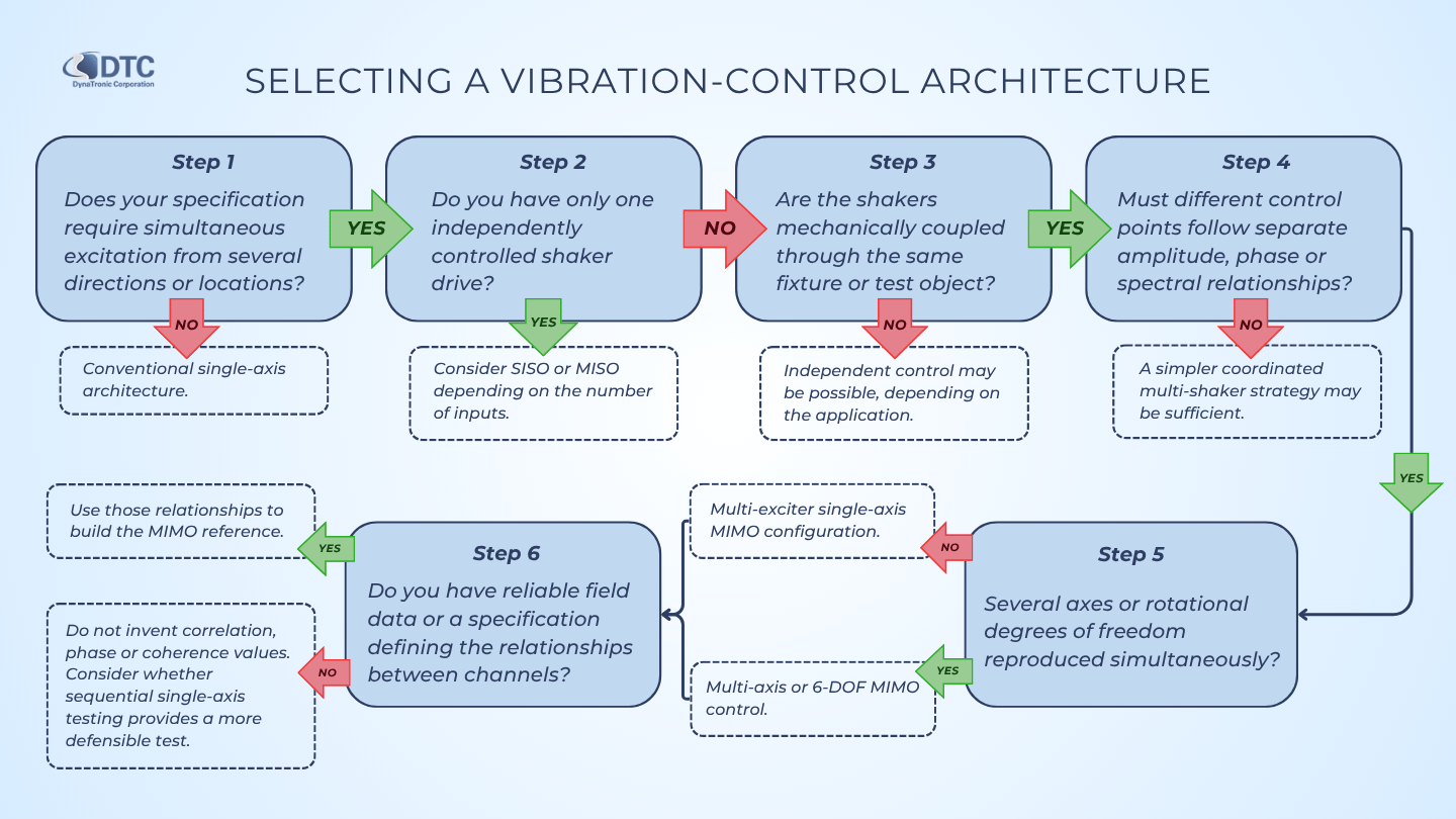
Step 1 — Does your specification require simultaneous excitation from several directions or locations?
No → Continue with a conventional single-axis architecture.
Yes → Go to Step 2.
Step 2 — Do you have only one independently controlled shaker drive?
Yes → Consider SISO or MISO control depending on the number of measurement/control inputs.
No → Go to Step 3.
Step 3 — Are the shakers mechanically coupled through the same fixture or test object?
No → Independent control may be possible, depending on the application.
Yes → Evaluate MIMO control.
Step 4 — Must different control points follow separate amplitude, phase or spectral relationships?
No → A simpler coordinated multi-shaker strategy may be sufficient.
Yes → MIMO is likely appropriate.
Step 5 — Are several axes or rotational degrees of freedom being reproduced simultaneously?
No → The setup may be a multi-exciter single-axis MIMO configuration.
Yes → Evaluate multi-axis or 6-DOF MIMO control.
Step 6 — Do you have reliable field data or a specification defining the relationships between channels?
Yes → Use those relationships to build the MIMO reference.
No → Do not invent correlation, phase or coherence values without engineering justification. Determine whether sequential single-axis testing would provide a more defensible test.
Five questions to ask before buying a MIMO vibration controller
A controller datasheet alone is not enough.
Ask the supplier:
1. How many independent outputs can actually be controlled?
Do not confuse output connectors with independently controlled MIMO drive channels.
2. How many control inputs can participate in the MIMO matrix?
Monitoring capacity and closed-loop control capacity may not be identical.
3. Which MIMO test modes are supported?
Confirm requirements for:
Sine
Random
Shock
Field data replication
Mixed-mode testing
4. How are phase, coherence and cross-spectral relationships entered and validated?
This is especially important for random and multi-axis environmental reproduction.
5. How is the coupled system identified before full-level control?
Understand how the controller identifies the transfer relationships between all shakers and control points and how changes in the specimen or fixture are handled.
Information to send when requesting a MIMO system recommendation
The quickest way to determine whether a test genuinely requires MIMO is to review the physical setup.
Prepare:
Test configuration
Drawing of the fixture
DUT dimensions and mass
Number of attachment points
Shaker locations
Excitation directions
Required axes
Existing shaker models
Power-amplifier models
Control requirement
Number of control accelerometers
Number of monitoring channels
Number of independent drive outputs
Required control method
Phase relationships
Coherence requirements
Limiting channels
Test profiles
Sine references
Random PSDs
Shock waveforms
Field time histories
Cross-power spectral data
Applicable qualification standards
System limits
Shaker force
Velocity
Displacement
Acceleration
Fixture mass
DUT mass
Providing these details allows the control architecture to be selected from the actual engineering problem instead of choosing hardware first.
Choosing Between Single-Axis, MISO and MIMO: Key Questions
-
No.
MIMO refers to a control architecture with multiple measurement inputs and multiple independent drive outputs.
A MIMO system can control several shakers operating along the same axis, or it can operate shakers along several axes.
Multi-axis describes the physical directions of excitation.
-
Not always.
A single-axis test may use one shaker but several control accelerometers. In that case, the physical test remains single-axis while the control system may use a MISO strategy.
-
MISO uses several measurement/control inputs but only one independent drive output.
MIMO uses several inputs and several independently controlled outputs.
-
Do I need MIMO if I use two shakers?
Potentially.
If two shakers are mechanically coupled through the same DUT or fixture, changes in one shaker can influence measurements associated with the other. MIMO may therefore be required to manage that interaction.
The exact requirement depends on the mechanical configuration and test objective.
-
Yes.
Two or more shakers can excite the same structure along one axis while being controlled as a coupled multiple-output system.
-
It can in applications where several directions that would otherwise be tested sequentially can validly be reproduced simultaneously.
However, reducing test duration should not be the main reason for converting a qualification test to MIMO. The test must first reproduce the required environment correctly.
-
No.
Accuracy depends on the test objective, reference data, fixture, sensor locations, controller setup and quality of the input specification.
A well-designed single-axis test can be more meaningful than a poorly defined MIMO test.
-
Cross-coupling occurs when the force from one shaker affects responses associated with other excitation or control locations.
Because the shakers are connected through the fixture and DUT, their actions are not necessarily independent.
-
Amplitude alone does not describe the relationship between several simultaneous vibration inputs.
Phase describes their relative timing, while coherence and cross-spectral information help describe how random signals at different control locations are related.
These relationships can significantly influence the resulting structural response.
-
Six-degree-of-freedom testing controls motion in three translational directions—X, Y and Z—and three rotational directions.
Such systems typically require several coordinated actuators and an appropriate MIMO control strategy.
-
If the system primarily needs one independently controlled shaker output with several measurement channels, a conventional VENZO configuration may be sufficient.
If several independently driven shakers interact through the same fixture or DUT and need simultaneous multi-point control, a VESSTA MIMO configuration should be evaluated.
Choose the control architecture from the test not the other way around
MIMO vibration testing can reproduce environments that are difficult or impossible to create with one independently controlled shaker.
But that does not make MIMO the automatic next step for every laboratory.
The correct progression is:
Understand the real environment → understand the structure → define the control points → define the excitation paths → then choose the controller.
For straightforward qualification work, conventional single-axis testing may provide the most reliable and efficient solution.
When one shaker remains sufficient but several measurement points need to influence control, MISO may provide the necessary visibility.
When several mechanically interacting shakers must produce independent, simultaneous references, the problem becomes MIMO.
And when the real requirement contains simultaneous translational and rotational motion, a multi-axis or six-degree-of-freedom architecture may be justified.
The goal is not to use the most complicated controller.
The goal is to reproduce the required vibration environment accurately, safely and repeatably.
Need help deciding between single-axis, MISO and MIMO?
Send DTC a drawing of your shaker and fixture configuration together with:
Shaker and amplifier models
DUT dimensions and mass
Number and position of excitation points
Required test axes
Number of control points
Test profiles or field measurements
DTC can review the setup and help determine whether a conventional VENZO 800 vibration controller, a VESSTA MIMO vibration controller, or another control configuration is appropriate.