
SRS vs Classical Shock Testing: What Is the Difference?
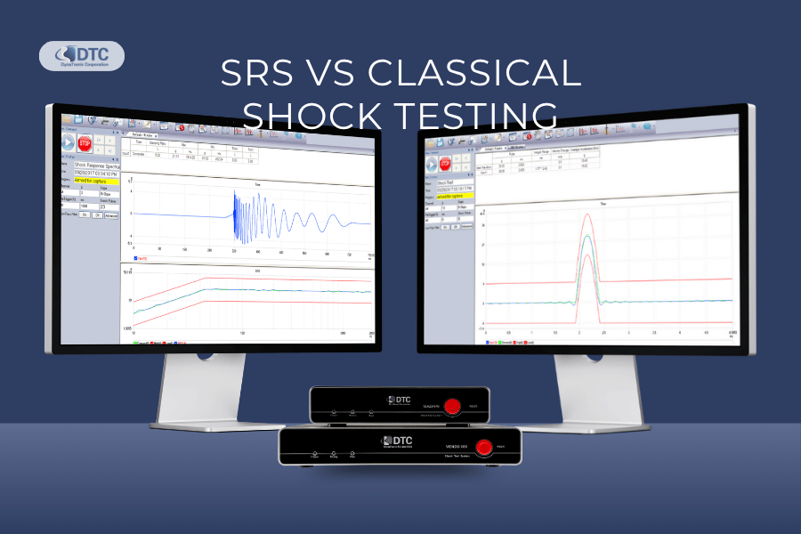
A product can experience mechanical shock when it is dropped, struck, transported, launched, separated from another structure or subjected to a sudden change in motion.
However, not every shock environment should be reproduced using the same test method.
Some requirements define a recognisable acceleration pulse, such as a half-sine or trapezoidal waveform. Others define the shock environment by the maximum response it could produce across a range of structural resonances.
These two approaches are commonly known as classical shock testing and shock response spectrum testing.
What is the difference between SRS and classical shock testing?
Classical shock testing specifies the acceleration pulse that must be applied to the test specimen. The requirement normally defines the waveform shape, peak acceleration, pulse duration, direction and number of shocks.
Shock response spectrum testing specifies how a range of idealised mechanical systems should respond to the shock. Instead of requiring one exact time-domain waveform, it defines the required response level across a range of natural frequencies and at a specified damping value.
In practical terms:
Classical shock asks: Did the machine produce the required pulse?
SRS asks: Did the pulse produce the required structural response across the specified frequency range?
The two methods are related rather than mutually exclusive. Every measured shock pulse can be converted into an SRS, including a half-sine or trapezoidal pulse. However, an SRS does not describe one unique pulse: different time-domain waveforms can produce similar shock response spectra. NASA has highlighted that an SRS requirement can be reproduced by multiple waveforms that may not resemble the original measured event.
SRS vs classical shock testing at a glance
| Comparison | Classical shock testing | SRS testing |
|---|---|---|
| Main test definition | Time-domain acceleration pulse | Frequency-domain response spectrum |
| Typical inputs | Pulse shape, peak acceleration and duration | Frequency, response level, damping and tolerance |
| Common pulse or profile | Half-sine, sawtooth or trapezoidal | Reference SRS curve |
| Primary question | Does the applied pulse match the requirement? | Does the shock create the required resonant response? |
| Best suited to | Defined impact, drop, bump and transport events | Complex transient, aerospace, defence and pyroshock environments |
| Result presentation | Acceleration versus time | Peak response versus natural frequency |
| Unique waveform required? | Generally yes, within specified tolerances | No; several waveforms may satisfy a similar SRS |
| Important additional parameters | Pulse duration, velocity change, direction and repetition | Damping or Q, frequency resolution and spectrum type |
| Typical test equipment | Shock machine, drop tester, bump tester or shaker | SRS-capable shock machine, shaker or transient test system |
| Main limitation | A simple pulse may not represent a complex real environment | The spectrum does not preserve every characteristic of the original waveform |
The required method should always be selected from the applicable product specification, test standard or measured service environment. One method should not be substituted for the other simply because it is easier to reproduce.
What is mechanical shock testing?
Mechanical shock testing evaluates how a product responds to a sudden input that occurs over a relatively short time.
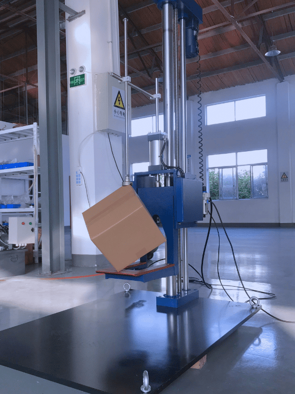
The event may result from:
Dropping a product or package
Impact during handling or transportation
A vehicle striking a pothole or obstacle
Sudden mechanical stopping
Equipment operation
Weapons firing
Stage or component separation
Pyrotechnic device activation
Crash or collision
Repeated bump events
Unlike continuous sine or random vibration, mechanical shock is transient. The test system must capture the event accurately before, during and after the pulse.
A shock test may be used to:
Identify mechanical weakness
Verify structural integrity
Detect loose components or connections
Evaluate functional performance during shock
Assess accumulated damage from repeated shocks
Reproduce a transportation or operational environment
Qualify equipment against an industry or customer specification
IEC 60068-2-27 provides a standard procedure for evaluating whether a specimen can withstand specified repetitive or non-repetitive shocks. The standard is written around prescribed pulse shapes and recommends choosing a severity and pulse shape that reproduce the expected transport or operational environment where possible.
What is classical shock testing?
Classical shock testing applies a defined acceleration pulse to the specimen.
The pulse is described directly in the time domain. This means that the test engineer can view acceleration on the vertical axis and time on the horizontal axis.
A classical shock requirement normally specifies:
Pulse waveform
Peak acceleration
Pulse duration
Positive and negative tolerance boundaries
Axis and direction
Number of pulses
Time between pulses
Specimen operating condition
Measurement location
Required pre-test and post-test inspections
For example, a requirement might specify a half-sine pulse with a defined peak acceleration and duration, applied several times in each direction along three perpendicular axes.
The test is accepted when the measured pulse remains within the specified tolerance boundaries and the specimen meets the required functional and structural criteria.
Common classical shock pulse shapes
Half-sine shock pulse
A half-sine pulse rises smoothly from zero to its maximum acceleration and then returns smoothly to zero.
It is widely used because it is relatively straightforward to define and reproduce. It may represent impacts where the acceleration builds and decays without a long constant section.
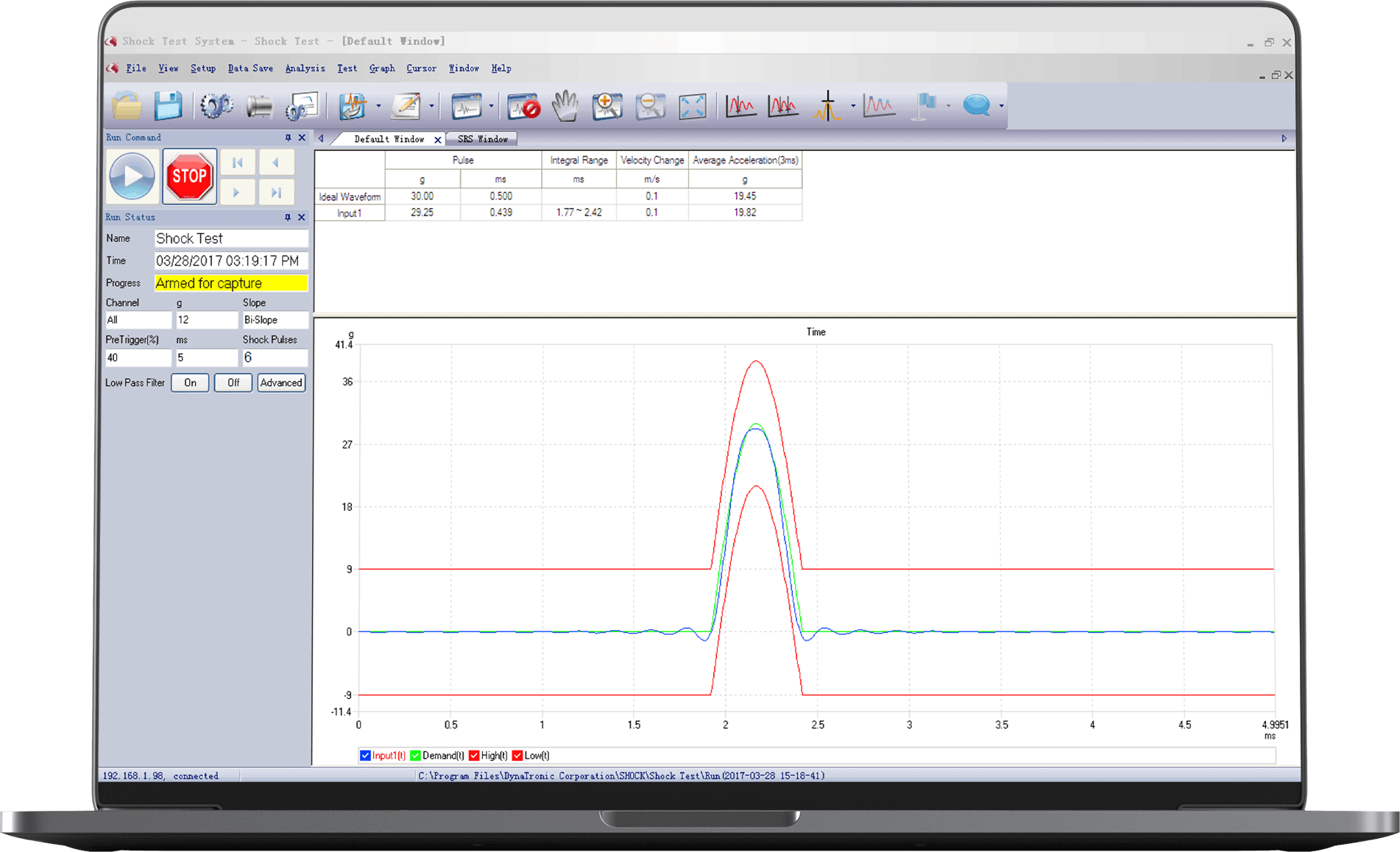
A half-sine requirement is primarily defined by:
Peak acceleration
Pulse duration
Pulse-shape tolerance
Velocity change
Direction and number of shocks
Pulse duration is critical. Two half-sine pulses with the same peak acceleration but different durations do not apply the same velocity change or excite the same range of structural frequencies.
Sawtooth shock pulse
A sawtooth pulse changes approximately linearly between its starting point and maximum acceleration.
Depending on the specification, the pulse may be described as an initial-peak or terminal-peak sawtooth. The selected orientation changes how the acceleration is distributed through the pulse duration.
The DTC VENZO 600 Series software includes support for final-peak sawtooth classical shock analysis.
Trapezoidal shock pulse
A trapezoidal pulse rises rapidly, remains near the specified acceleration for a defined interval and then returns to zero.
Because acceleration is maintained for part of the event, a trapezoidal pulse can produce a greater velocity change than a shorter curved pulse with the same peak acceleration.
It may therefore impose a different severity on structures, fasteners and internal components even when the headline peak-g value appears similar.
Other pulse shapes
A product specification may require another waveform, a user-defined pulse or an actual recorded time history.
The correct waveform should be taken from the controlling specification rather than selected solely according to what the shock machine can reproduce most easily.
What does a classical shock test measure?
The principal measurement is the actual acceleration time history at the control or reference location.
The controller or transient acquisition system evaluates characteristics such as:
Measured peak acceleration
Pulse duration
Pulse shape
Positive and negative portions of the pulse
Velocity change
Trigger position
Pre-pulse and post-pulse behaviour
Pulse repeatability
Compliance with the tolerance boundaries
Additional accelerometers may be installed on the test specimen to measure how critical components respond.
The reference accelerometer confirms what the shock machine applied. Response accelerometers show what different parts of the specimen experienced.
These values can be very different when the fixture or specimen contains structural resonances.
When is classical shock testing appropriate?
Classical shock testing is usually appropriate when:
The governing standard specifies a pulse shape
A drop, bump or impact can be represented adequately by a defined pulse
The acceptance criteria are based on peak acceleration and duration
Production testing requires a repeatable, easily compared waveform
The test is intended to identify general structural weakness
The customer or certification requirement explicitly calls for classical shock
It is commonly used for components, electronic assemblies, packaged equipment, automotive parts, industrial equipment and products exposed to transportation or handling shocks.
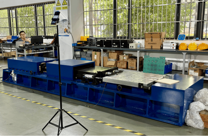
Advantages of classical shock testing
Classical shock testing provides several practical advantages:
The test requirement is relatively easy to communicate.
The pulse can be examined directly in the time domain.
Peak acceleration and duration are easy to compare.
Standard pulse shapes support repeatability between laboratories.
The test can be suitable for production and qualification programmes.
Test tolerances can be displayed clearly around the target pulse.
Limitations of classical shock testing
A simple pulse does not always represent a complex field environment.
Two events may have the same peak acceleration but distribute their energy very differently across time and frequency. As a result, they may excite the specimen’s natural frequencies differently.
Classical shock results can therefore be misleading when engineers focus only on peak acceleration.
A 100 g pulse is not automatically more damaging than a 60 g pulse. Pulse duration, velocity change, frequency content, structural resonances, damping and specimen design all influence the resulting response.
This is one reason SRS analysis is valuable.
What is a shock response spectrum?
A shock response spectrum describes how a set of idealised single-degree-of-freedom systems would respond to a measured shock pulse.

Imagine a collection of simple mass-spring-damper systems:
Each has a different natural frequency.
Each is subjected to the same base acceleration time history.
Each uses the same specified damping ratio.
The maximum response of each system is calculated.
These maximum values are plotted against natural frequency to create the SRS.
NASA describes the SRS as a long-established method for analysing shock response and notes that it is widely used to describe certain spacecraft vibration and shock environments for equipment qualification.
What does an SRS tell the engineer?
The SRS estimates the maximum response that structures with different natural frequencies could experience when exposed to the measured shock.
It helps answer questions such as:
Which structural frequencies experience the strongest response?
Could a component resonance amplify the shock?
How severe is a complex transient across the required bandwidth?
Does a laboratory-generated pulse meet the target response spectrum?
How do two different shock events compare?
Does a measured event remain below the qualification limit?
The SRS does not show exactly when each response occurred. It retains the maximum response calculated for each oscillator frequency.
How is an SRS different from a Fourier spectrum?
A Fourier spectrum breaks a time signal into its frequency components.
An SRS estimates the maximum response of damped mechanical oscillators subjected to that signal.
The two tools therefore answer different questions:
A Fourier spectrum asks: What frequency components are present in the signal?
An SRS asks: How strongly could systems with different natural frequencies respond?
A Fourier spectrum is not a replacement for an SRS when a shock qualification requirement is defined by structural response.
An SRS is not a unique time waveform
One of the most important facts about SRS testing is that a reference SRS does not define one exact time history.
Many different waveforms may produce the same or a similar response spectrum.
They may differ in:
Pulse shape
Peak acceleration
Duration
Phase
Polarity
Oscillation pattern
Velocity change
Time localisation
Positive and negative acceleration balance
This gives engineers flexibility when synthesising a laboratory test pulse, but it also creates risk.
A waveform may satisfy the SRS tolerance while differing from the real environment in ways that affect the specimen. For critical applications, the test team may therefore need to evaluate the time history, velocity change, displacement, duration and other criteria in addition to the SRS. NASA has specifically identified the many-to-one relationship between an SRS and its possible time waveforms as a limitation of SRS-only specifications.
How to read a shock response spectrum
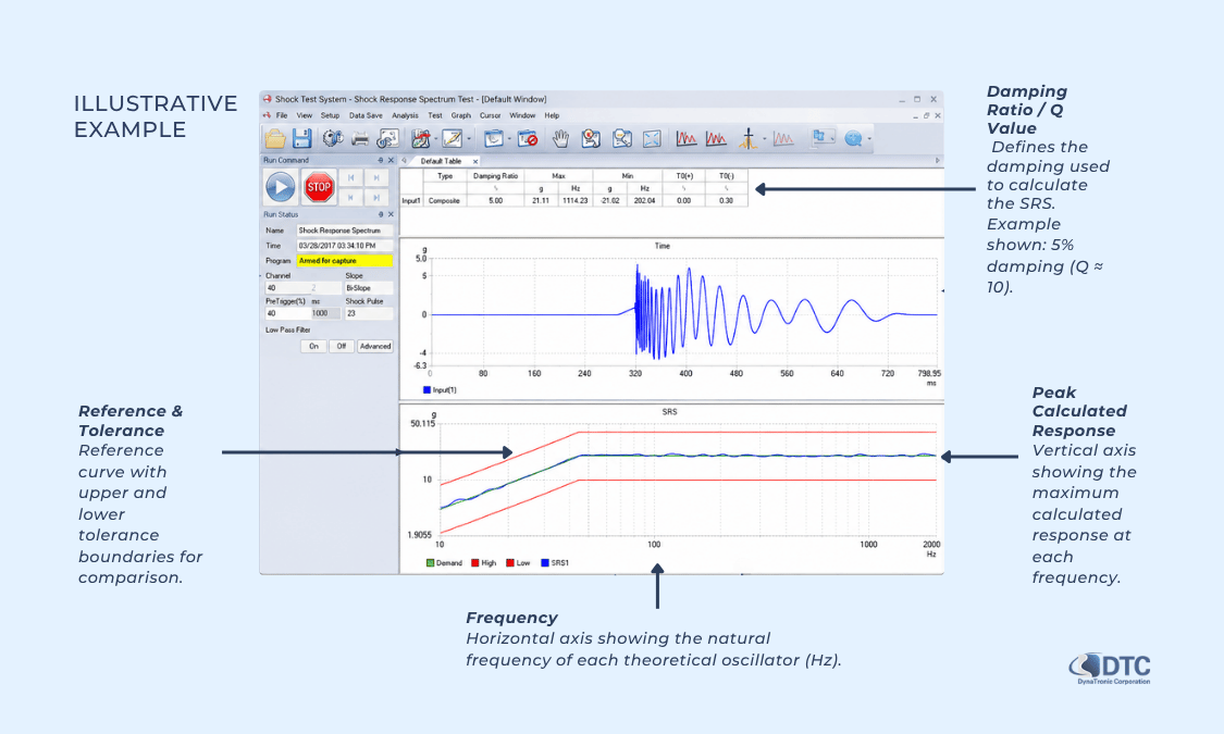
An SRS graph normally presents:
Frequency on the horizontal axis
Peak calculated response on the vertical axis
A specified damping ratio or Q value
A reference curve and tolerance boundaries
A defined frequency resolution
Both axes are often logarithmic because the test may cover a wide range of frequencies and acceleration levels.
Natural frequency
Each point along the horizontal axis represents the natural frequency of an idealised single-degree-of-freedom oscillator.
It does not necessarily mean that the test specimen has a resonance at every plotted frequency. The curve represents the responses of the theoretical oscillator bank used in the calculation.
Response level
The vertical axis commonly shows peak acceleration response, although other SRS formats can use relative displacement, velocity or pseudo-velocity.
The required format and units must be confirmed before comparing spectra.
Damping ratio and Q factor
Damping controls how quickly an oscillator’s response decays.
A lightly damped oscillator can produce a larger resonant response than a heavily damped oscillator exposed to the same pulse.
The quality factor, or Q, is commonly related to the damping ratio by:
Q = 1 ÷ (2 × damping ratio)
For example:
5% damping corresponds approximately to Q = 10.
2% damping corresponds approximately to Q = 25.
10% damping corresponds approximately to Q = 5.
This means that two SRS curves calculated from the same time history cannot be compared properly unless they use the same damping or Q value.
The required damping should be taken from the test specification. It should not be changed simply to make the measured curve pass within tolerance.
Frequency resolution
SRS calculation frequencies may be spaced at fractional-octave intervals.
A smaller interval provides more calculation points and a more detailed curve, but it also increases processing and reporting detail.
The appropriate resolution depends on:
The controlling specification
Frequency range
Expected structural resonances
Required comparison accuracy
Controller and analysis capabilities
DTC’s VENZO 600 Series supports SRS resolutions from 1/1 to 1/48 octave with user-defined reference frequencies.
Primary, residual and composite SRS
Different portions of the response can be reported depending on the test requirement.
Primary SRS
The primary SRS records the maximum response occurring while the shock input is being applied.
It describes the strongest calculated response during the pulse itself.
Residual SRS
The residual SRS records the maximum response after the input pulse has ended, while the theoretical oscillator continues to ring down.
This can be important for short shocks that excite continued structural oscillation after the main event.
Composite SRS
The composite SRS takes the maximum relevant response over the complete analysis period.
It provides a combined view that includes the pulse and subsequent residual response.
The DTC VENZO 600 Shock Test System supports primary, residual and composite SRS analysis.
The test specification should identify which spectrum is required. A primary spectrum should not be compared directly with a residual or composite requirement.
Why can two shocks with the same peak acceleration produce different results?
Peak acceleration is only one characteristic of a shock pulse.
Consider two events that both reach 100 g:
The first is a short, narrow pulse.
The second lasts considerably longer.
One contains high-frequency oscillation.
The other is comparatively smooth.
One changes velocity significantly.
The other produces a smaller net velocity change.
Although both events have the same peak acceleration, they may excite completely different parts of the specimen.
A low-frequency structural mode may respond strongly to one pulse and only slightly to the other. A small electronic component with a high natural frequency may show the opposite behaviour.
The SRS exposes these differences by calculating response across a range of natural frequencies.
For this reason, engineers should avoid using peak-g values alone to compare shock severity.
Classical shock testing versus SRS testing: which should you use?
The governing specification should be the first decision point.
Do not convert a classical requirement into an SRS requirement—or an SRS requirement into a convenient half-sine pulse—without engineering justification and approval from the responsible authority.
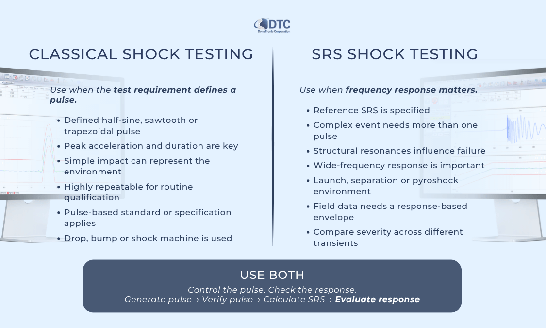
Choose classical shock testing when:
The specification defines a half-sine, sawtooth or trapezoidal pulse.
Peak acceleration and pulse duration are the main acceptance criteria.
The expected environment can be represented by a relatively simple impact.
The test must be highly repeatable for routine qualification or production.
The product is being evaluated against IEC 60068-2-27 or another pulse-based requirement.
A drop, bump or shock machine is intended to generate a defined pulse shape.
Choose SRS testing when:
The requirement is provided as a reference SRS.
The source event is complex and cannot be represented adequately by one simple pulse.
Structural resonances are important to the expected failure mechanism.
Qualification is based on response across a wide frequency range.
The environment involves launch, separation, pyrotechnic or other severe transient events.
Field measurements need to be converted into a response-based qualification envelope.
The laboratory must compare the potential severity of several different transients.
SRS is used extensively in spacecraft and pyroshock work because these events can contain complex, high-frequency structural responses. NASA notes that spacecraft shock environments can contain meaningful SRS content extending into the kilohertz range.
In some cases, use both:
Classical pulse control and SRS analysis can be used together.
For example, a laboratory may:
Generate a half-sine pulse.
Confirm that its peak acceleration, duration and shape meet the classical requirement.
Calculate its SRS.
Evaluate whether the pulse creates excessive response at critical frequencies.
Record response channels on the specimen.
This provides more information than peak acceleration and duration alone.
What equipment is required for classical shock testing?
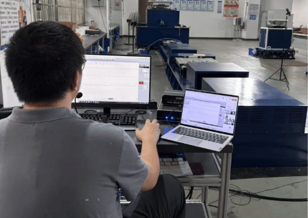
A classical shock test system may include:
Drop tester, bump machine, shock machine or electrodynamic shaker
Shock controller or transient acquisition system
Reference accelerometer
Response accelerometers
Suitable signal conditioning
Fixture and specimen mounting
Trigger or machine-status interface
Data-acquisition computer
Safety and machine-control connections
The selected machine must be capable of generating the required pulse within tolerance.
The controller must be able to:
Capture the complete event
Trigger reliably
Include sufficient pre-trigger data
Measure the required pulse duration
Identify the peak acceleration
Display tolerance boundaries
Calculate velocity change where required
Store and report every pulse
Support the required sensor inputs and sampling rate
What equipment is required for SRS testing?
An SRS test may use:
A specialised shock response spectrum machine
A mechanical impact or shock machine
An electrodynamic shaker where the required waveform and physical limits permit
A transient recorder or shock controller
High-bandwidth shock accelerometers
Appropriate signal conditioning
A rigid fixture
SRS calculation and comparison software
Sufficient sampling and anti-alias filtering
Pre-trigger and post-trigger recording
The physical test machine must be able to produce a waveform whose calculated SRS remains within the required tolerance.
The controller or analysis system should support:
Reference spectrum entry
Breakpoint calculation
Frequency-range selection
Fractional-octave spacing
Damping or Q definition
Primary, residual or composite analysis
Trigger configuration
Time-history recording
SRS tolerance comparison
Test-report generation
DTC’s VENZO 600 Series is designed to acquire and analyse signals from drop, bump and shock machines. Its software supports classical shock, SRS, transient capture and vibration analysis. The system provides capture durations from 1 to 10,000 milliseconds and selectable sampling frequencies up to 204.8 kHz for SRS and transient capture applications.
Sensor selection for shock and SRS testing
Shock measurement places different demands on an accelerometer than routine low-level vibration measurement.
An unsuitable sensor can overload, saturate, resonate or introduce false high-frequency content into the result.
Check the measurement range
The accelerometer must withstand the expected peak acceleration without electrical or mechanical overload.
Include reasonable allowance for:
Pulse overshoot
Fixture response
Local structural resonance
Unexpected machine behaviour
High response at specimen locations
A sensor selected only according to the target peak may still overload if the actual fixture response exceeds the nominal test level.
Check the usable frequency range
The sensor, mounting method and signal-conditioning system must support the frequency range required for the pulse and SRS analysis.
High-frequency shock measurement is particularly sensitive to:
Accelerometer resonance
Mounting stiffness
Mechanical filtering
Cable motion
Connector movement
Electrical noise
Grounding
Anti-alias filtering
Select the appropriate output type
Depending on the environment, the measurement system may use:
IEPE shock accelerometers
Charge-output accelerometers
Piezoelectric sensors with external conditioning
Mechanically filtered accelerometers
High-g specialised shock sensors
DTC provides vibration and shock sensors intended for high-magnitude, short-duration events as well as general vibration measurements.
Mount the accelerometer correctly
A loose or flexible mounting method can introduce artificial resonance and distort the measured shock.
For demanding shock measurements, stud mounting or another validated high-stiffness method may provide better high-frequency behaviour than a thick adhesive layer or magnetic mounting.
The mounting approach should be selected according to:
Sensor specification
Test frequency range
Surface material
Available mounting space
Expected acceleration
Need to protect the specimen
Sampling, filtering and triggering considerations
Sampling rate
The sampling rate must be high enough to capture the pulse and the required analysis bandwidth.
However, sampling rate alone does not guarantee accurate data. The complete acquisition path also includes:
Sensor bandwidth
Signal conditioner
Analogue input range
Anti-alias filter
Analogue-to-digital converter
Trigger configuration
Data-processing software
A high sampling rate cannot recover information that was distorted by sensor resonance, clipping or unsuitable analogue filtering.
Trigger level
The trigger must activate reliably when the shock begins without being activated prematurely by noise.
The test engineer may need to define:
Trigger channel
Positive, negative or bi-slope trigger
Trigger acceleration level
Percentage of the expected pulse
Pre-trigger percentage
Trigger delay
The DTC VENZO 600 Series supports rising, falling and bi-slope triggering, selectable trigger channels and up to 100% advance pre-trigger capture.
Pre-trigger data
Pre-trigger recording helps establish the baseline immediately before the event.
Without sufficient pre-trigger data, it can be more difficult to identify:
Baseline offset
Electrical noise
Previous vibration
An early part of the pulse
Premature triggering
Sensor instability
Filtering
Filtering should remove unwanted noise without eliminating valid shock content or creating artificial oscillation.
Aggressive filtering can change:
Peak acceleration
Pulse duration
Velocity change
High-frequency response
Calculated SRS
The applied filter type, cutoff frequency and processing method should be documented in the test report.
Common mistakes in classical shock and SRS testing
1. Comparing shocks only by peak acceleration
Peak acceleration does not fully describe pulse duration, velocity change, frequency content or resonant response.
Always review the complete time history and, where relevant, its SRS.
2. Treating an SRS as a time-domain waveform
An SRS is a response curve, not a unique acceleration pulse.
Several different waveforms may satisfy the same spectrum.
3. Comparing SRS curves calculated with different damping
Changing damping changes the calculated oscillator response.
Confirm that the measured and reference spectra use the same damping ratio or Q value.
4. Ignoring the SRS type
Primary, residual and composite spectra are not interchangeable.
Use the spectrum type required by the controlling specification.
5. Using an unsuitable accelerometer
Sensor overload or resonance may produce distorted time histories and unrealistic high-frequency SRS values.
6. Using an insufficient sampling rate
A short transient or high-frequency SRS requirement may not be represented correctly if the complete measurement bandwidth is inadequate.
7. Allowing clipping in the acquisition chain
Once a sensor, conditioner or input channel clips, the true pulse cannot be reconstructed reliably.
Set the input range with sufficient headroom before testing.
8. Ignoring velocity change and displacement
A synthesized pulse may meet the SRS while demanding excessive machine displacement or creating an unrealistic velocity change.
The waveform must remain physically achievable and appropriate for the intended environment.
9. Measuring only at the machine table
The table measurement confirms the input, but response channels may be necessary to identify amplification at the fixture, enclosure or critical component.
10. Using an outdated or incorrect standard revision
Standards and customer specifications may be revised.
Always follow the version specified by the contract, certification programme or responsible engineering authority. The current IEC listing identifies IEC 60068-2-27:2008 as the valid edition, with a stability date of 2028.
Information to prepare before requesting a shock test system
Before selecting a controller, acquisition system or shock machine, prepare the following information.
Test requirement
Classical shock or SRS
Governing standard and revision
Target pulse or reference spectrum
Tolerance boundaries
Frequency range
Damping ratio or Q
Number of shocks
Test axes and directions
Required specimen operating condition
Expected signal
Peak acceleration
Pulse duration
Expected velocity change
Sampling requirement
SRS frequency range
High-frequency content
Required capture duration
Trigger method
Test equipment
Shock-machine type and model
Drop, bump or shaker configuration
Available machine interfaces
Fixture type
Existing controller or recorder
Required machine-control signals
Sensors
Number of reference channels
Number of response channels
Sensor type
Sensitivity
Measurement range
Frequency range
IEPE or charge conditioning
Mounting method
Reporting and operation
Required report format
Pulse acceptance calculation
SRS export format
Need for offline analysis
Continuous recording
Test automation
Calibration requirements
Future test expansion
How DTC supports classical shock and SRS testing
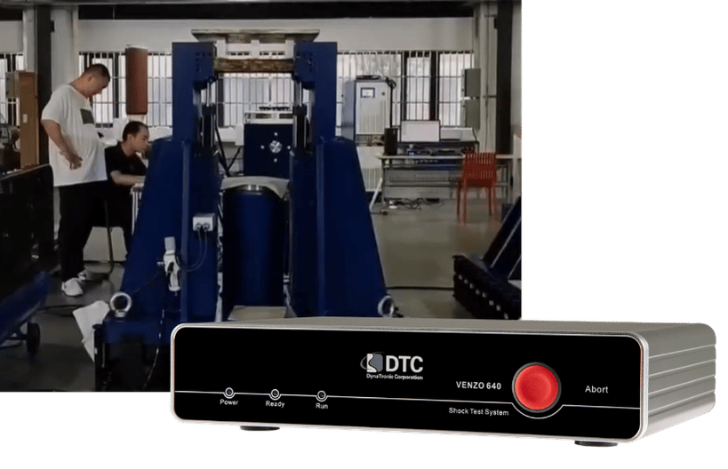
The DTC VENZO 600 Series Shock Test System, including VENZO 640 and VENZO 680 configurations, supports:
Classical shock analysis
Half-sine waveforms
Final-peak sawtooth waveforms
Trapezoidal waveforms
User-defined classical shock requirements
Shock response spectrum analysis
Primary, residual and composite SRS
Resolution from 1/1 to 1/48 octave
User-defined reference frequencies
Adjustable damping ratios
Transient capture
Pre-trigger recording
Selectable trigger levels and slopes
Continuous data recording
Vibration analysis
Automatic test reports
The free VENZO 640/680 demonstration software allows engineers to review the classical shock, SRS, transient capture and reporting environment before selecting a system.
Engineers can also review DTC’s SRS and transient-capture videos, download the latest VENZO 640 and VENZO 680 datasheets, or evaluate suitable shock accelerometers.
Frequently asked questions:
Is an SRS a shock pulse?
No.
An SRS is a curve showing the calculated maximum response of a series of damped single-degree-of-freedom systems across a range of natural frequencies.
A time-domain shock pulse is used to calculate the SRS.
Can a classical shock pulse have an SRS?
Yes.
Every valid acceleration time history can be processed to produce an SRS. A half-sine, sawtooth, trapezoidal or measured field pulse can therefore be evaluated in both the time and response-spectrum domains.
Can two different shock pulses have the same SRS?
Different waveforms can produce the same or very similar SRS curves.
This is why the time history, duration, velocity change, polarity and machine limits may also need to be evaluated when creating an SRS test waveform.
Is SRS testing more severe than classical shock testing?
Not automatically.
Severity depends on the specific pulse or reference spectrum, frequency range, damping, duration, specimen resonances and acceptance limits.
A classical pulse may be more severe for one structure, while an SRS-defined waveform may be more severe for another.
Is SRS testing only used for pyroshock?
No.
SRS is strongly associated with aerospace and pyroshock applications, but it can be used to analyse any transient acceleration event where structural response across frequency is important.
What is the difference between primary and residual SRS?
Primary SRS identifies maximum response while the input pulse is active.
Residual SRS identifies maximum response after the input has ended and the theoretical oscillators are ringing down.
A composite spectrum considers the relevant maximum response over the complete period.
What Q value should be used for SRS analysis?
Use the Q value or damping ratio defined by the governing specification.
Do not select Q only according to which value gives the most favourable result. The reference and measured SRS must be calculated using the same value.
Can an electrodynamic shaker perform SRS testing?
An electrodynamic shaker may reproduce certain synthesized shock waveforms when its force, acceleration, velocity, displacement and bandwidth are sufficient.
Very high-level, short-duration or high-frequency requirements may require another type of shock machine.
The complete waveform and shaker limits should be reviewed before testing.
Do classical shock and SRS require different controllers?
Not necessarily.
Some shock test systems support both classical pulse analysis and SRS calculation. However, the system must provide the required acquisition bandwidth, trigger functions, input range, software and machine integration.
What information does DTC need to recommend a shock test system?
Provide:
The target pulse or SRS
Test standard and revision
Frequency range
Peak acceleration
Pulse duration
Damping or Q
Number of measurement channels
Sensor types
Shock-machine model
Required trigger and machine-control functions
Reporting requirements
Get the right system for your shock test requirement
Classical shock and SRS testing describe mechanical shock in different ways.
Classical shock defines the pulse applied to the specimen through parameters such as shape, peak acceleration and duration.
SRS defines the maximum response that the pulse should produce across a range of natural frequencies at a specified damping value.
Neither method is universally better. The correct approach depends on the governing requirement, expected environment, product structure, failure mechanism and capabilities of the test equipment.
DTC can help evaluate:
Whether the requirement is classical shock, SRS or both
The appropriate VENZO 640 or VENZO 680 configuration
Sampling and capture requirements
Reference and response-channel quantities
Trigger and machine-control needs
Suitable shock accelerometers
Reporting and analysis requirements
Contact DTC and send the target pulse, reference SRS or test standard to receive a recommended shock measurement and control configuration.