
How to Choose a Vibration Controller for Your Shaker

Selecting a vibration controller is not simply a matter of comparing channel counts or sampling rates.
The controller must work as part of the complete vibration test system, including the shaker, power amplifier, accelerometers, fixtures, test specifications and safety limits. A controller with impressive specifications can still be the wrong choice if it cannot run the required test profiles, communicate correctly with the amplifier or support the necessary control strategy.
How do you choose the right vibration controller?
To choose a vibration controller for an existing or new shaker, first define:
The vibration tests you need to perform
The shaker and amplifier you need to control
The required control, monitoring and limiting channels
The number of independent drive outputs
The accelerometers and other sensors you will use
The required frequency range, dynamic range and sampling performance
The safety, abort and limiting functions needed
Your future expansion, calibration and support requirements
The best controller is not necessarily the model with the highest number of channels. It is the controller that can safely reproduce your required test environment, obtain reliable feedback from the test article and integrate with the rest of your laboratory equipment.
This guide explains how to evaluate those requirements before selecting or replacing a shaker controller.
What does a vibration controller do?
A vibration controller manages the closed-loop operation of a vibration test system.
During a typical test:
The controller generates a drive signal.
The signal is sent to the shaker’s power amplifier.
The amplifier powers the shaker.
Accelerometers measure the actual vibration at the control point and other locations.
The controller compares the measured response with the required test profile.
The drive signal is continuously adjusted to keep the test within the defined reference and safety limits.
Unlike a basic signal generator, a vibration controller uses feedback from the test system to maintain the required vibration level. It must respond to changes caused by the shaker, fixture, specimen mass, structural resonances and other system behaviour.
The controller is therefore both the command centre and an important protection layer for the shaker, specimen and test personnel.
1. Start with the tests you need to perform
The first question should not be, “Which controller has the most channels?”
It should be: “What types of tests must this system run today, and what might it need to run in the future?”
Sine vibration testing
Sine testing applies vibration at defined frequencies and amplitudes. It may be used for resonance searches, resonance dwell tests, swept-sine testing and structural response evaluation.
When evaluating a controller for sine testing, consider:
Required frequency range
Sweep rate
Acceleration, velocity or displacement control
Resonance search and tracking
Dwell capability
Compression and tension limits
Harmonic measurement
Notching and limiting requirements
A controller intended only for basic sine sweeps may not provide the same control, analysis and protection functions required for more advanced qualification testing.
Random vibration testing
Random vibration testing reproduces a broadband environment using a power spectral density, or PSD, reference profile.
Important controller capabilities may include:
Real-time closed-loop PSD control
Frequency resolution
Degrees of freedom
Control strategy
Sigma clipping
Kurtosis control, where required
Notching and response limiting
Automatic level scheduling
Test abort conditions
Continuous data recording
Random vibration testing can place significant demands on the shaker and amplifier. The controller should allow the engineer to enter the shaker’s force, acceleration, velocity and displacement limits so the planned profile can be reviewed before the test begins.
Classical shock testing
Classical shock testing uses defined transient waveforms such as half-sine, trapezoidal or sawtooth pulses.
A controller used for classical shock must capture the complete transient event and manage the drive waveform, triggering, compensation and displacement requirements. The required sampling rate, sensor range and transient storage should be evaluated against the expected pulse duration and acceleration level.
If shock response spectrum testing is a primary requirement, confirm that the selected control system and software are designed for the required SRS workflow rather than assuming that every vibration controller provides the same shock capability.
Field data replication
Field data replication, sometimes called time waveform replication, reproduces a measured time history on a laboratory shaker.
The controller must be able to import or process the recorded waveform, compensate for the test system response and reproduce the target within the physical limits of the shaker and amplifier.
The DTC VENZO 800 Series Vibration Controller supports sine, random, classical shock and field data replication workflows.
Do you need single-axis or MIMO control?
A large number of measurement channels does not automatically make a controller suitable for multi-axis or multi-shaker control.
A conventional single-axis test usually uses one drive output. Additional inputs may be used for control averaging, monitoring, limiting or data recording.
A multi-input multi-output system may require several independent drive outputs and control algorithms that account for the interaction between multiple shakers and control points.
Consider a dedicated MIMO controller when the test requires:
Several shakers operating on the same specimen
Independent drive signals
Multiple controlled axes
Defined phase relationships
Cross-coupled control
Multi-point reference profiles
Multi-degree-of-freedom vibration reproduction
DTC’s VESSTA MIMO Vibration Controller is designed for multiple-shaker excitation, multiple control points and MIMO sine, random, shock and field data replication.
2. Check compatibility with the shaker and amplifier
A vibration controller is normally connected to the power amplifier rather than directly driving the shaker.
Before replacing a controller or adding one to an existing test system, document the complete signal path:
Controller → power amplifier → shaker → fixture and specimen → control accelerometer → controller
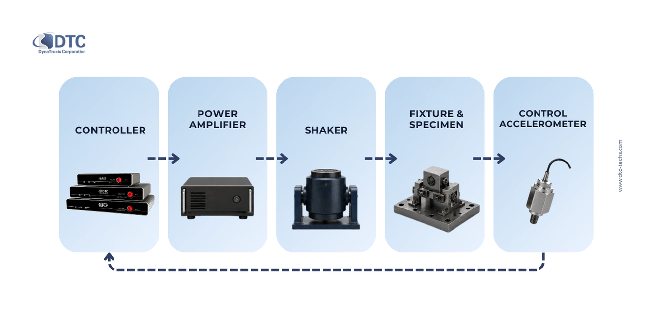
The new controller must be evaluated against the electrical, mechanical and operational characteristics of this system.
Identify the shaker type
Start by confirming whether the system uses:
An electrodynamic shaker
A servo-hydraulic shaker
A servo-electric actuator
A single shaker
Multiple mechanically connected shakers
A vertical armature
A horizontal slip table
A specialist multi-axis configuration
Controller manufacturers offer systems that can be configured for different shaker technologies, but compatibility should always be confirmed for the specific amplifier, feedback arrangement and control mode. Competing controller manufacturers also identify compatibility with existing electrodynamic and servo-hydraulic shakers as a major consideration when replacing a controller.
Record the amplifier interface
The controller and amplifier must exchange the correct signals.
Collect the following information:
Amplifier make and model
Analogue drive-input range
Input impedance
Required drive polarity
Amplifier gain
Emergency stop and abort connections
Interlock signals
Field supply status signals
Cooling-system status
Fault outputs
Remote control requirements
Do not assume that a controller can be connected safely because the drive connectors appear physically compatible.
The expected voltage range, grounding configuration, polarity and abort wiring should be checked before commissioning.
Know the shaker’s operating limits
The controller should be configured with the shaker system’s actual limits, including:
Maximum force
Maximum acceleration
Maximum velocity
Maximum displacement
Maximum armature current
Maximum specimen mass
Maximum frequency
Amplifier voltage and current limits
These parameters help determine whether a proposed test profile can be run without exceeding the shaker’s operating envelope.
However, the controller cannot compensate for an undersized shaker. If the required test demands more force, velocity or displacement than the shaker can produce, a different controller will not solve the underlying mechanical limitation.
Consider the complete moving mass
The shaker does not move only the test specimen.
The required force is influenced by:
Armature mass
Fixture mass
Slip-table components
Specimen mass
Head expander
Cables and auxiliary equipment
Dynamic response of the assembly
A heavy or flexible fixture may introduce resonances and increase control difficulty. Controller selection should therefore be performed alongside a review of the fixture and shaker capability.
3. Determine how many input channels you need
Input channels receive signals from the control accelerometer and other sensors.
A basic test may use one control accelerometer, but many real test configurations require more inputs.
Control channels
Control channels provide the feedback used to regulate the test.
Depending on the test configuration, the controller may use:
One control point
An average of several control points
A minimum or maximum control strategy
Weighted control
Multiple independent control points
Using several control accelerometers can be helpful when testing a large fixture or specimen where vibration is not uniform across the mounting surface.
Monitoring channels
Monitoring channels record response at locations that do not directly control the drive signal.
They may be used to observe:
Critical components
Fixture response
Structural resonances
Connector locations
Printed circuit boards
Battery modules
Enclosures
Mounting interfaces
These channels help engineers understand how the test article responds, even when only one location is used for control.
Limiting channels
A limiting channel helps protect the specimen or fixture.
For example, the test may be controlled at the fixture interface while another accelerometer monitors a sensitive component. If the response at that component exceeds the permitted level, the controller can reduce the drive or stop the test.
Data-recording channels
Some laboratories need to record a larger number of response channels than are required for closed-loop control.
Before purchasing the controller, decide whether all measurements should be handled by the controller or whether a separate dynamic data acquisition and analysis system will be used.
A separate DAQ can be useful when the test requires extensive structural, acoustic, strain or multi-point response measurement beyond the control system’s normal channel configuration.
Plan channel capacity from the test layout
Create a channel list before choosing the hardware.
| Measurement purpose | Example quantity |
|---|---|
| Primary control accelerometer | 1 |
| Additional control points | 2 |
| Fixture limiting channels | 2 |
| Specimen response channels | 4 |
| Spare channels | 1 |
| Total required | 10 |
In this example, a controller limited to eight channels would not meet the complete requirement, even though only one channel controls the shaker.
Leave reasonable capacity for future fixtures, additional limiting points and new qualification requirements. Buying exactly the minimum number of channels can create another upgrade requirement sooner than expected.
4. Determine how many drive outputs you need
The number of input channels and output channels serves different purposes.
Inputs receive signals from accelerometers and other sensors.
Outputs send independent drive commands to amplifiers.
A conventional single-shaker, single-axis test normally requires one drive output.
Two outputs may be required for certain dual-shaker, dual-axis, phase-controlled or specialised configurations. More complex MIMO systems may require four, eight or more independent outputs.
Do not select a controller for multi-shaker testing based only on the presence of a second physical output. Confirm:
Whether each output can be independently controlled
Which software modules are required
Whether the control algorithm accounts for cross-coupling
The supported number of control loops
Synchronisation between outputs
Phase-control capability
Safety behaviour if one shaker or amplifier faults
Improper control of mechanically connected shakers can create unwanted forces, phase errors or unsafe loading. Multi-shaker tests therefore require a controller and control strategy intended for that configuration.
5. Confirm sensor and signal-conditioning compatibility
The controller receives its feedback through accelerometers, so sensor compatibility is part of controller selection.
Document the sensor types currently used in the laboratory and those expected in future tests.
These may include:
IEPE accelerometers
Charge-output accelerometers
Voltage-output sensors
TEDS-enabled sensors
High-g shock accelerometers
Miniature accelerometers
Triaxial accelerometers
Velocity transducers
Displacement sensors
Force transducers
Check the input type
An IEPE accelerometer requires a constant-current supply. A charge-output accelerometer may require an external or integrated charge amplifier. A TEDS sensor requires compatible reading and configuration functions if its digital identification is to be used.
DTC offers general-purpose, miniature and triaxial IEPE accelerometers, charge-output sensors and shock sensors for different vibration measurement requirements.
Before choosing a controller, verify:
Supported input signal types
IEPE power availability
Input voltage range
Charge support
TEDS support
AC and DC coupling
Anti-alias filtering
Sensor sensitivity entry
Engineering-unit conversion
Overload indication
Match sensor range to the test
A high-sensitivity accelerometer can provide good resolution at low vibration levels but may overload during a high-g test. A lower-sensitivity sensor may tolerate greater acceleration but provide less resolution for very small signals.
Controller and sensor selection should therefore be based on the complete measurement range, not only the maximum acceleration in the test specification.
Do not overlook sensor mounting
Poor sensor mounting can distort the measured signal, especially at higher frequencies.
The controller can only respond to the signal it receives. Loose mounting, unsuitable adhesive, cable movement, grounding problems or an incorrectly oriented accelerometer can all affect test accuracy.
6. Evaluate sampling rate, frequency range and dynamic performance
Technical specifications such as sampling rate and bit depth are important, but they should be interpreted in the context of the test.
Sampling rate
The sampling rate indicates how frequently the controller digitises the input signal.
A higher sampling rate can support wider measurement bandwidths and shorter transient events, but the useful capability also depends on:
Analogue input bandwidth
Anti-alias filters
Control-loop processing
Test software
Number of active channels
Data storage and transfer
Required frequency resolution
Do not select a controller based on sampling rate alone.
Frequency range
Confirm that the controller supports the required lower and upper frequencies for every test mode.
Low-frequency tests may be limited by shaker displacement and sensor response. High-frequency tests may be limited by the shaker, fixture, accelerometer mounting and structural resonances rather than the controller.
Bit depth and dynamic range
Bit depth describes the resolution of the analogue-to-digital conversion, but it does not by itself describe the complete usable dynamic range.
Noise floor, input range, analogue design, grounding, signal conditioning and sensor quality all influence the smallest usable signal. Dynamic range is particularly important when a test must control low-level vibration while also monitoring higher-amplitude responses.
Spectral resolution
For sine and random testing, frequency resolution affects how finely the controller can represent or analyse the spectrum.
Higher resolution may be helpful when:
Resonances are closely spaced
Narrowband behaviour is important
Detailed PSD control is required
Structural modes must be identified
A test specification defines narrow frequency transitions
However, more spectral lines are not automatically necessary for every routine production test.
7. Review safety, limiting and abort functions
Safety should be treated as a primary selection criterion, not an optional software feature.
A vibration controller should help protect:
The shaker
The power amplifier
The fixture
The test specimen
Accelerometers and cables
Laboratory personnel
Depending on the system and test method, useful protection functions may include:
Maximum drive limit
Acceleration limit
Velocity limit
Displacement limit
Force limit
Response limiting
Notching
Open-loop detection
Sensor overload detection
Loss-of-signal detection
Amplifier fault input
Emergency abort output
Automatic level reduction
Test shutdown
Event logs
The controller should stop or reduce the test predictably when a control accelerometer disconnects, an amplifier reports a fault or a limiting channel exceeds its threshold.
Before purchasing, ask how the controller behaves during each failure condition. It is better to define this during system selection than during an actual qualification test.
8. Evaluate the software, not only the hardware
Engineers spend more time using the controller software than looking at the controller hardware.
The software should make it practical to create, review, run and document tests.
Evaluate the following functions:
Test creation
Can engineers create profiles efficiently?
Can existing profiles be imported?
Are engineering units handled correctly?
Can schedules and test levels be reviewed before running?
Can shaker limits be included in the setup?
Can profiles be reused without accidental changes?
Test visibility
During the test, the operator should be able to see:
Reference and control levels
Drive signal
Response channels
Limiting channels
Test progress
Warnings
Shaker limits
Abort conditions
Data and reports
Consider whether the software can:
Store test configurations
Record time histories
Export measurement data
Generate test reports
Include plots and test information
Add operator or specimen details
Review completed tests offline
Maintain traceability between the profile and result
User management
For laboratories with several operators, ask whether the software supports:
Different user permissions
Protected test templates
Audit trails
Standardised reporting
Controlled access to safety parameters
Multiple systems from one computer
DTC provides free VENZO 800 demonstration software that can simulate sine, random, classical shock and transient capture tests, calculate parameters such as RMS, force and shaker limits, and generate simulated reports.
Testing the software before purchasing can reveal workflow issues that are not visible in a datasheet.
9. Consider calibration, maintenance and technical support
A vibration controller is a measurement and control instrument. Its long-term value depends on more than the initial hardware purchase.
Ask the supplier about:
Calibration interval
Traceability
Factory and local calibration options
On-site calibration
Software updates
Firmware updates
Remote diagnostics
Spare equipment
Operator training
Application support
Warranty
Response time for technical issues
Support for older hardware
DTC provides calibration tools and support for voltage, charge, IEPE and TEDS vibration transducers using several calibration methods.
For laboratories operating under quality-management or accreditation requirements, the controller’s calibration documentation and service process should be reviewed before purchase.
10. Plan for future expansion
A controller may remain in service longer than the shaker, amplifier or current test programme.
Consider what could change over the next several years:
Additional control points
Larger specimens
More response measurements
New testing standards
A second shaker
Multi-axis testing
Field data replication
More advanced shock testing
Automated test sequences
Integration with laboratory software
Additional test stands
Expansion can involve more than installing another input card. Ask whether expansion requires:
New hardware
A different chassis
Additional software licences
Factory configuration
New calibration
A different control architecture
A modular system may reduce the need to replace the complete controller when channel requirements increase.

Can you replace the controller without replacing the shaker?
In many cases, an older vibration controller can be replaced while retaining the existing shaker and power amplifier.
However, replacement should only proceed after reviewing:
Shaker type and condition
Power amplifier interface
Drive-signal requirements
Abort and interlock wiring
Existing accelerometers
Required test modes
Fixture and specimen requirements
Shaker operating limits
Calibration and commissioning
Controller manufacturers commonly position replacement control hardware as a way to modernise an existing shaker system, but the specific compatibility and commissioning requirements must still be verified for each installation.
A controller replacement may be appropriate when:
The existing software is no longer supported
Replacement parts are unavailable
The laboratory needs additional channels
Modern reporting is required
New test methods are being introduced
Existing hardware cannot be calibrated
Operators need a more manageable software environment
Before requesting a recommendation, collect photographs of the current controller and amplifier connections, electrical documentation and the shaker nameplate.
Choosing between DTC VENZO 800 Series controllers

The VENZO 800 Series is designed for shaker-based sine, random, classical shock and field data replication testing.
The current series includes three principal configurations.
| Model | Expandable input capacity | Drive outputs | Maximum sampling rate | Input/output resolution |
|---|---|---|---|---|
| VENZO 820 | Up to 8 channels | 1 | Up to 204.8 kHz | 24-bit |
| VENZO 880 | Up to 32 channels | 2 | Up to 204.8 kHz | 24-bit |
| VENZO 8160 | Up to 64 channels | 2 | Up to 204.8 kHz | 24-bit |
The three models also provide up to 25,600 lines of spectral resolution.
When to consider VENZO 820
VENZO 820 may be suitable when:
The system uses one shaker and one drive output
The required control and monitoring configuration fits within eight channels
The laboratory runs standard sine, random, shock or replication tests
A compact channel configuration meets foreseeable requirements
When to consider VENZO 880
VENZO 880 may be appropriate when:
More control, limiting or response channels are needed
The test layout may grow beyond eight channels
Two output channels are required for a supported configuration
The laboratory needs greater expansion capacity
When to consider VENZO 8160
VENZO 8160 may be appropriate when:
Tests require a high number of monitoring or response channels
Large fixtures or specimens use multiple measurement locations
The laboratory wants capacity for future expansion
Several test configurations must be accommodated by one controller platform
The final choice should not be based on these examples alone. Software modules, exact channel configuration, output use, sensors and shaker compatibility should be confirmed with DTC before ordering.
For complex multi-axis or multi-shaker control, evaluate whether a dedicated VESSTA MIMO system is more appropriate than a conventional single-axis controller with a high input-channel count.
Download a Free Practical Engineering Checklist on how to choose a vibration controller
Information to prepare before requesting a controller recommendation
Providing complete information helps the controller supplier evaluate the application more accurately.
Existing equipment
Shaker manufacturer and model
Power amplifier manufacturer and model
Current controller
Slip table or head expander
Fixture type
Existing accelerometers
Photographs of connections
Shaker and amplifier manuals
Test requirements
Sine, random, shock or field data replication
Required testing standards
Frequency range
Acceleration level
Velocity and displacement
PSD profiles
Shock pulse duration and peak
Specimen mass
Fixture mass
Number of tests per day
Required test duration
Channel requirements
Number of control accelerometers
Number of limiting channels
Number of monitoring channels
Number of independent drive outputs
Other sensor types
Required spare capacity
Operational requirements
Report format
Data export
Remote operation
User permissions
Calibration requirements
Training
Installation
Software-update policy
Future expansion
Common mistakes when choosing a vibration controller
Choosing by channel count alone
More channels are only valuable when they support a defined measurement or control requirement.
Ignoring the amplifier interface
Electrical incompatibility, incorrect grounding or missing abort connections can delay commissioning and create safety risks.
Confusing monitoring channels with control channels
A controller may record many response channels but use only a smaller number in the closed control loop.
Assuming two outputs provide full MIMO control
MIMO testing requires appropriate control algorithms, software, synchronisation and system architecture—not merely additional connectors.
Buying only for the current test
A controller that exactly meets today’s minimum requirement may become restrictive when another fixture, sensor or test method is introduced.
Focusing only on sampling rate
Sampling rate should be considered together with bandwidth, filtering, dynamic range, channel count, processing and the actual test method.
Treating software as an afterthought
Difficult test creation, reporting or data review can consume more laboratory time than a small difference in hardware specifications.
Overlooking calibration and support
A controller that cannot be calibrated or supported efficiently may create downtime and quality-system problems later.
Frequently asked questions:
What is the most important factor when choosing a vibration controller?
The most important factor is whether the controller can safely and accurately run the required test profile with the specific shaker, amplifier, sensors and specimen configuration.
Channel count, sampling rate and software features should be evaluated after the complete test requirement is understood.
Will a new vibration controller work with my existing shaker?
It may be possible to replace the controller while retaining the shaker and amplifier, but compatibility should be confirmed.
The supplier will need information about the shaker, amplifier, drive interface, abort wiring, sensors and required test methods.
How many vibration-controller channels do I need?
Count every required control, limiting, monitoring and recording signal. Then include reasonable spare capacity for future tests.
A single-shaker test may still require several input channels even though it uses only one drive output.
What is the difference between an input channel and an output channel?
An input channel receives a measurement signal from an accelerometer or another sensor. An output channel sends a drive command to a power amplifier.
Multiple measurement points do not necessarily require multiple drive outputs.
Do I need a separate DAQ system?
A separate DAQ may be useful when you need to record substantially more response channels, perform additional signal analysis or measure signals that are not part of the vibration-control loop.
For simpler tests, the controller’s available monitoring channels may be sufficient.
Is a higher sampling rate always better?
Not necessarily.
The sampling rate must be sufficient for the required bandwidth and transient behaviour, but useful performance also depends on filtering, analogue bandwidth, dynamic range, software and the number of active channels.
Can one controller operate several shakers?
Some systems can control multiple shakers, but the correct architecture depends on whether the shakers operate independently, in phase, on multiple axes or as a coupled MIMO system.
The configuration should be reviewed by the controller and shaker specialists before operation.
Should I choose the largest controller to allow future expansion?
Not automatically.
Unused capacity adds cost, while insufficient capacity creates future limitations. The best approach is to define likely expansion scenarios and choose a controller that can accommodate them without significantly oversizing the current system.
Get a vibration controller recommendation for your shaker
Choosing the correct vibration controller requires more than matching a controller model to a shaker nameplate.
The test method, amplifier interface, sensors, control strategy, safety limits, software and future expansion must all be considered as one system.
DTC supports laboratories and manufacturers using electrodynamic and servo-hydraulic shaker systems with vibration control hardware, software, sensors, calibration support and practical engineering guidance.
To receive a recommended configuration, send DTC:
Your shaker and amplifier models
The tests you need to perform
The required control and monitoring channels
Your accelerometer types
Your current test profiles or standards
Any future expansion requirements
Talk to a DTC engineer about your vibration test setup, review the VENZO 800 Series, or download the latest controller datasheets and technical resources.